INTRODUCTION
Therapy using implantable deep-brain stimulation (DBS) system is widely used to treat many diseases [e.g., Parkinson's disease (PD) and obsessive-compulsive disorder]1,4,10). Prior to clinical tests, preclinical research must be conducted in order to clarify the mechanism involved in the treatment, to prevent from side effects, and to establish a more effective and reliable procedure3,7,14). To enable this, an implantable DBS system, which is suitable for preclinical tests, is required although several types of systems have been developed, they have been unsuitable for preclinical study2,8,9,11,12).
For example, the first type of such systems consisted of an electrode implanted in the body for stimulation, with the stimulator located outside the body, and a wire connecting the electrode and stimulator. The disadvantages of this system included risk of infection and a limitation in free activity of the animals and discomfort due to the wire. The second type was fully implantable system with a built-in battery, which removed the risk of infection and the limitation in activity. However, this system required replacement of the battery and a sizable place for the implantation, and hence, was not suitable for long-term use. The third type of system solved the problems described above by using a wireless power transmission technology in a special cage. However, the problem of requiring a special cage for transmitting power to the implanted device was still present.
Therefore in this study, we have proposed a fully implanted DBS system completely suitable for preclinical research. To overcome the drawbacks presented above, we suggest distinct functions such as wearable wireless power transfer (WPT), changing of parameters through the external controller, and a status indicator.
The advantages of the proposed system are as followings : 1) long-term stability of the system, 2) free activity of the experimental animal, 3) the ability to change the amplitude of the stimulus, 4) information on implanted device status. To validate the system, we conducted experiments on PD-rodent models for 4 weeks. We confirmed that our system functions well and does not generate any harmful effect when used long-term.
MATERIALS AND METHODS
Technical description
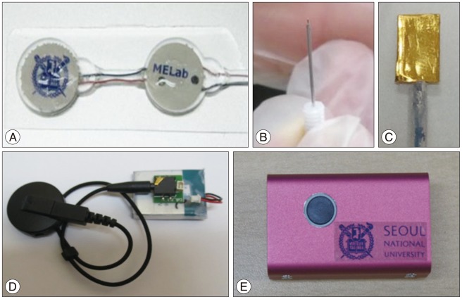
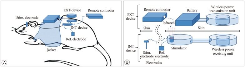
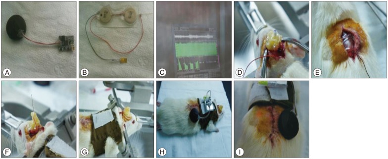
The system consisted of four parts (Fig. 1) : 1) internal device for stimulation circuit, IR receiver, wireless power receiving unit (Fig. 1A), 2) electrodes (Fig. 1B, C), 3) external device for wireless power transmission unit (Fig. 1D), and 4) external controller for changing stimulation parameters (Fig. 1E). System configurations are shown in Fig. 2. The stimulation electrode was inserted into the head, and the reference electrode and the stimulator were inserted into the subcutaneous area on the back. The stimulation electrode and internal device were connected with a wire through the subcutaneous tissue in the neck. External device was composed of a wireless power transmission unit, a battery. Wireless power transmission unit and the battery were fixed within a jacket with a magnet (Fig. 2A). The remote controller was used only for changing parameter. The details of the system are shown in Fig. 2B.
Electrodes
For stimulating electrodes, a commercially available concentric stainless steel electrode (PlasticsOne, Roanoke, VA, USA) was used. The total length of the electrode was 17 mm, and the external tube had 15 mm and 2 mm opening. A 10√ó5 mm rectangular gold (99.9%; Sigma-Aldrich, Saint Louis, MO, USA) was used as a reference electrode. In the experiment, a unipolar system consisting of one commercial electrode and a reference electrode was used.
Internal devices
Stimulator
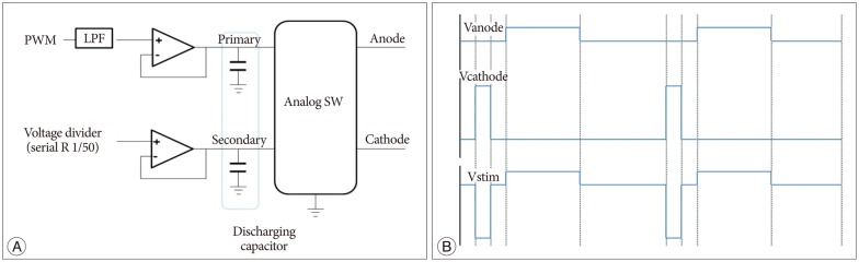
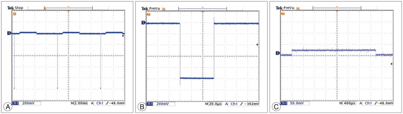
Stimulator consisted of a Micro controller (MSP430F2013, TI), a stimulating waveform generator, and a data receiver (IR LED). The stimulating waveform was generated by the following process and Fig. 3A shows block diagram for biphasic pulse stimulation. First, the pulse-width modulation (PWM) waveform was generated by the Micro controller. Then, a primary discharging capacitor is charged by an op-amp buffer, and simultaneously, a secondary discharging capacitor is also charged by a voltage divider. The charge of the capacitors is converted into an asymmetric biphasic pulse by analog switches. Since an unbalanced stimulus pulse results in a net ion flow, tissue damage, and corrosion of anode electrode surface, a charge-balanced waveform is important. As shown in Fig. 3B, one channel of the circuit generated a square pulse (Vcathode) and another channel generated a delayed square pulse (Vanode : amplitude of 1/50, duration of 50 pulses). This resulted in the generation of a charge balanced biphasic stimulus pulse (Vstim) from Vcathode and Vanode. In the cathode pulse, stimulus current depolarized nearby axons and initiated the action potential, and the anodic pulse cancelled the charge accumulated by the cathode pulse. By controlling the PWM signal, the amplitude of the waveform can be controlled. The external IR remote enabled voltage control with a 0.1 V increase. We configured a basic setting of waveform as 60 µs, 130 Hz, and 1.0 V.
Wireless power receiving unit
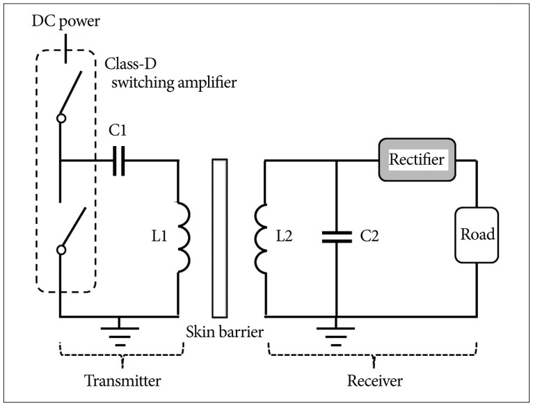
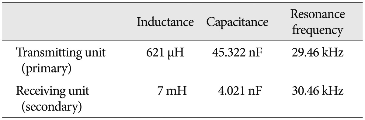
The wireless power transmission system consisted of a full-bridge rectifier and a secondary coil, which could receive the power based on the principle of inductive coupling13). Fig. 4 illustrates the receiver, consisting of L2 (7 mH), C2 (4.021 nF), and the full-bridge rectifier. To maximize the transmission efficiency, the resonance frequency was chosen as 30 kHz.
External device
Wireless power transmission unit-wearable WPT
Wireless power transmission system was designed to have a Class-D power amplifier, which enables the primary coil to generate magnetic field and the implanted secondary coil to generate current. PWM signal was generated by the Micro controller (MSP430F2013, TI) and a Class-D switching amplifier chip (TC4420, TI)5,13). As shown in Fig. 4, PWM frequency was 30 kHz, which was chosen as the resonant frequency of the L1 (621 µH) and C1 (45.322 nF).
Remote controller
The external controller controlled the amplitude of the stimulation waveform by utilizing IR LED. The initial amplitude was 1.0 V, and it is designed to be increased from 0-3 V by 0.1 V increment.
Encapsulation (coating procedure)
To protect the circuit after implantation of the internal device, we put the circuit in a hard inner case made up of polyether ether ketone (PEEK). In addition we coated the outside of the device with poly(dimethylsiloxane) (PDMS), which is a biocompatible and water repellent substance, and hence, suitable for coating implantable device.
The procedure was as follows : PDMS monomer and polymerase were mixed in a 10 : 1 proportion. Bubbles were eliminated by putting in a vacuum chamber for 30 min. The inner case, which is made up of PEEK with PDMS was filled thoroughly with PDMS before putting the circuit. Curing was conducted in the pre-heated oven at 60‚ÑÉ. At the same time, 1 mL PMDS was added to the mold and cured under the same condition to build a basic layer on the mold. After completing step 4, the internal system was put in the mold after eliminating the extra PDMS stuck on the inner case. The empty spaces were filled with PDMS without generating bubbles. Curing was conducted for 1.5 h at 60‚ÑÉ.
Experimental set-up
Animal model preparation
We induced PD by injecting 6-hydroxydopamine (6-OHDA) (12 µg/3 µL) into the right medial forebrain bundle in the rat brain using a stereotaxic frame. 6-OHDA is known to show selective neurotoxicity to catecholaminergic neurons, and it is reported that 6-OHDA also induces PD-like behavioral similarity in primates when injected into the substantia nigra. The PD-rat model was prepared by the following procedure : 1) Rats (250-300 g) were placed on a stereotaxic frame plate. A hemostatic machine was used to maintain the body temperature throughout the procedure. 2) The horizontal alignment was checked holding the ear bar of the frame in the rat's ears. 3) A skin incision was made and the membrane on the skull was stripped away by using a swab. 4) Indicate the injection site (AP : -4.4 mm, ML : -2.1 mm, DV : -7.8 mm) and drill a hole. 5) A Hamilton syringe filled with the required amount of 6-OHDA (3 µL) was delivered to the target depth (-7.8 mm) and the drug was infused slowly (0.25 µL/min). 6) Apomorphine-induced rotation tests, which checks for loss of dopaminergic neuron, were performed from the first week on alternate weeks. Uniaxial rotational movement was observed after hypodermic injection to the back of the neck in PD-animals.
Histology
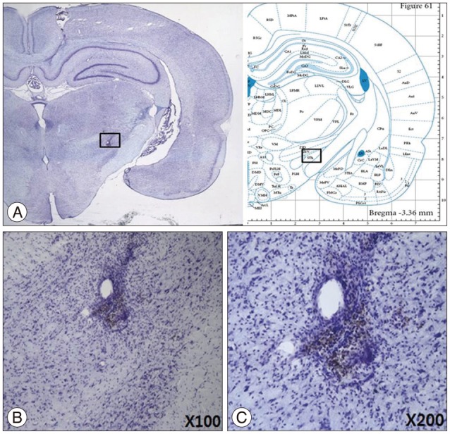
At the completion of the last behavior experiments, each rat was deeply anesthetized and perfused transcardially with about 50 mL of 0.9% NaCl (with heparine), followed by about 50 mL of ice-cold 4% paraformaldehyde. After perfusion, the rat brains were removed and placed, for one day, in a 50 mL conical tube containing ice-cold 4% paraformaldehyde. The rat brains were then transferred sequentially at one-day intervals into 10%, 20%, and 30% sucrose until they sank to the bottom of their container. The rat brains were then entirely cut into 30 µm-thick coronal sections on a freezing cryostat (Leica CM 3000, Leica, Solms, Germany). Every fifth section was collected for staining with cresyl violet to confirm the electrode trajectory at the nuclei [subthalamic nucleus (STN)].
Implantation procedure (surgery)
Surgery was performed as follows (Fig. 5) : four-week-old PD animals were anesthetized by injecting 75 mg/kg zoletil 50 and 10 mg/kg xylazine. They were fixed to the stereotaxic frame once anesthetized. Dorsal surface skin around skull was incised to show the bregma. The electrode was fixed on a holder and the frame was controlled to make the upper side of skull leveled out. A hole was drilled at 3.4 mm behind the bregma and 2.6 mm next to the center-line by using a hand drill. A hole was also drilled for holding two to three anchors. STN was detected by inserting an electrode ventrally while measuring nerve signal using the microelectrode recoding (MER) system (storage oscilloscope, Lead Point, Minneapolis, MI, USA). Electrodes were fixed to the anchors by aid of medical grade epoxy. An incision was made along the lower dorsal spine sagittally. Then, subcutaneous path in the direction of skull for electrode cables and a subcutaneous region to implant the internal device was identified. The implantable device was inserted across the spine and sutured with the surrounding muscle tissue for support. Then, the device was connected to the electrodes through the subcutaneous tissue, before suturing the incision. The electrode and a cable were connected by using medical epoxy. The body temperature was maintained by an infrared warmer, until the rat was stabilized.
Microelectrode recording procedure
Extracellular recordings were performed in STN from dopamine-depleted animals. The impedance of the micro-targeting electrodes was 1.8-2.4 MΩ. The neuronal signals were amplified and filtered (-3 dB at 500 Hz and 5 kHz) and displayed on a MER system (LeadPoint, Minneapolis, MI, USA). During microelectrode recording experiments, anesthesia was maintained and the stereotaxic frame was placed in a Faraday cage shield, covered with copper-mesh-plates to exclude the interfering electromagnetic signals from the environment. The amplitude size of the wave was recorded along trajectories aimed at STN in the brain of rat PD-model by a MER system with one channel recording.
Behavioral test (apomorphine-induced rotation)
Behavior test was as follows : 1) The stimulus was given for 4 weeks after the implantation before conducting the behavior test. 2) R-apomorphine hydrochloride (0.5 mg/kg; Sigma-Aldrich, Saint Louis, MO, USA) dissolved in 0.1% ascorbate-saline was injected into the animals. Immediately, the subject was placed on a 42 cm diameter plastic hemisphere and the total number of turns per time (total number of turns=normal number of turns-inverse number of turns, counterclockwise in this experiment) were recorded for each animal. 3) A commercial product (Rotation Activity Test system by Iwoo system, Seoul, Korea) was used to count the total number of turns.
RESULTS
Performance test in vitro
Performance of stimulation
The performance tests for the circuits were conducted twice. We could get the same test results of the output waveform before and after encapsulation. We observed the output waveform when only resister components existed by connecting a 1 kΩ resister and measured the power that the circuit consumed. Initial setting of asymmetric biphasic pulse was generated for 130 Hz of frequency, 60 µs pulse width, and 1 V amplitude.
To expect the in vivo output waveform, we observed the output waveform after connecting the experimental electrodes and dipping them in physiological saline. In the physiological saline test, generated waveform distortion did not occur, which was similar to the result obtained with the 1 kΩ resister test. Moreover, there were no side effects, such as air bubbles on the electrode surface, over a one-hour test period (Fig. 6). The output increased linearly with a 0.1 V increment, according to the external remote control.
Performance of wearable WPT
As mentioned before, the wireless power transmission system consists of transmission unit and receiving unit. The inductor (L) and capacitor (C) were selected to set the resonance frequency as 30 kHz (Table 1). Neodymium magnet was used to solve misalignment of coils by fixing them6). In addition, we tested the uptime of the system based on 500 mAh lithium-polymer battery. The test was conducted while the distance between the transmission unit and the receiving unit was fixed as 2 mm. The results of the test showed that the system was operable for 24 h based on a 500 mAh lithium-polymer battery.
Performance test in vivo
Device operating test
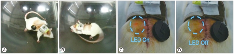
We tested the behavior and implanted device status one week after implanting the device in three PD models wearing the jacket with the external device and battery. The PD models were moving freely as illustrated in Fig. 7A and B. Through the red LED light of the implanted device, the working status of the device could be confirmed (Fig. 7C, D).
Behavior test
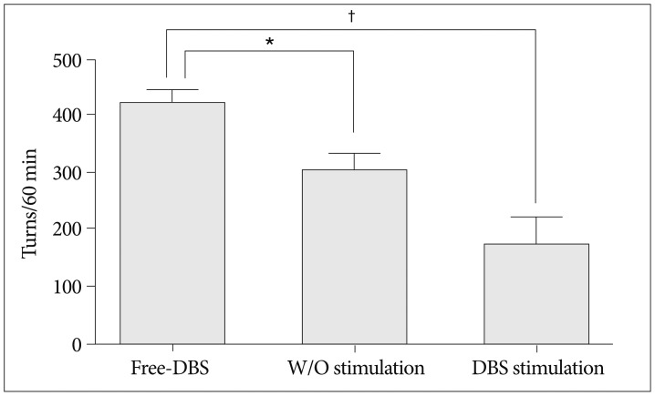
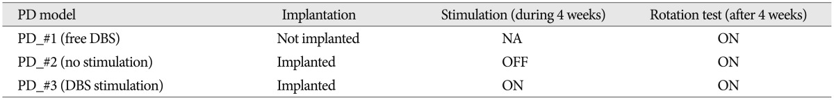
The effectiveness of the device was verified through the rotation test, as shown in Table 2 and the possibility of long-term experiment was confirmed through the four-week experiment. We implanted the device in two (PD_#2 and PD_#3) of the three PD models, but gave stimulus to only one (PD_#3) of the two models (1.0 V, 130 Hz, 60 µs). After four weeks, the rotation tests were conducted on each model. As illustrated in Fig. 8, PD_#1, which did not get the device, had the greatest number of turns. We also confirmed that PD_#3, under stimulation for four weeks, had the lowest number of turns. In addition, based on the number of turns of PD_#2, it was clear that the symptom could be relieved just by implanting the device.
System validation
Pathology
To test the safety of the implantable device, we checked if brain region stimulated by the implanted electrodes was damaged four weeks after the implantation. From the analyses of the brain sections from the test animals, corresponding to the site of the electrodes, there was no damaged tissue near the region of implantation, as shown in Fig. 9.
Safety and effectiveness
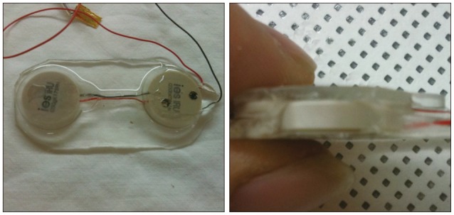
The stability of the device was verified four weeks after the implantation by checking the status of the device. Fig. 10 shows that the capsule did not have any problem after long-term implantation. In addition, we confirmed the effectiveness of the output performance by comparing the output waveform before and after the implantation.
DISCUSSION
In this study, we developed a DBS system using WPT technology, which is suitable for long-term preclinical tests in freely moving animal models. Through the in vitro test, we confirmed that the electrical stimulation neither caused any side effect nor damaged the electrodes. Through the in vivo animal PD model experiment, we verified that the stimulation helped to alleviate the symptoms, and the tissues around the electrodes were not damaged.
Fully implantable DBS system
Our DBS system, using wearable WPT, overcomes problems that traditional built-in battery DBS systems usually have. Although there are other systems using WPT, they require a special huge cage to transfer power into an implanted device. However, our system has the distinct wearable WPT system, which enables size reduction by being battery-less system and does not require any device or cage. Through the four-week in vivo test, we confirmed the possibility of a long-term test without any limitation in activity.
Functions of parameter change and one-way data communication
Our system has the ability to change the parameters of the stimulation waveform, which is necessary to get a variety of data from long-term animal experiments. After the implantation, the voltage levels of the stimulation can be changed by the external controller using IR communication (from 0-3.0 V, 0.1 unit increment). The status of the device is checked by the red LED on the implanted device, through the skin. Although our system has only a few passive elements, it is sufficient to communicate from the external to the implanted device. This is a big advantage of our system as compared to several large active communication devices (e.g., RF module, bluetooth module, zigbee module) that lead to an increased power consumption. Hence, our system is a suitable communication method for semi-permanent implant devices.
CONCLUSION
If we have overall the above-mentioned features, our DBS system has main distinctions which are wearable WPT and communication function using a few passive elements. Suitability for the pre-clinical test and effectiveness, safety, stability were verified through the in vitro and in vivo tests. Also, we considered our system would be useful to study a long term impact of deep brain stimulation in the future.