INTRODUCTION
Several methods have been developed to achieve fixation of the subaxial cervical spine either through screws/rods constructs or wire/cable techniques. Posterior cervical screw instrumentation has been reported to have higher fusion rates than posterior wiring and does not require rigid external mobilization for treating cervical spine instability5,32). Insertion of screws in the lateral mass is employed routinely in cervical spine. Although it is a relatively safe and easy surgical procedure, lateral mass screw fixation at C7 can be problematic23,28,31). Construct failure due to the loosening or avulsion of the screws has been reported, particularly in the lower cervical spine where decreasing size of the lateral mass results in a decreased amount of the minimal pull-out strength required9,14).
Screw insertion into the cervical pedicle has been proposed as an alternative technique30). Pedicle screw fixation is considered to be the most biomechanically stable when performed through a posterior-only approach18). However, this procedure can be technically difficult and potentially dangerous, as the cervical pedicle is small and is immediately surrounded by delicate structures : laterally by the vertebral artery (VA), medially by the spinal cord, and vertically by adjacent nerve roots7,8,16,38). Anatomic variations in pedicle trajectory and morphology make pedicle screw placement using standard bony landmarks potentially dangerous17,24). Moreover, as up to 5% of patients have a VA in the C7 transverse foramen, pedicle fixation at this level is anatomically dangerous4). Even under direct visualization in a cadaveric study or in experienced surgical hands, pedicle breaches have been reported up to 23% of the time15,29). Computer-assisted navigation systems are also inconvenient as they increase surgical time in the operating room1,2).
Recently, intralaminar screws have been used as a potentially safer alternative to traditional fusion constructs involving fixation of C2 and the upper thoracic spine19,36,37). We have also described a novel technique of intralaminar screw fixation of the subaxial cervical spine and reported case series with successful outcome using this method9,11,13). The intralaminar screw method is useful for avoiding vascular injuries, especially when the VA tracks in the C7 transverse foramen. Also, it maintains a high degree of stability in the subaxial cervical spine9). This technique has two key advantages over the currently used surgical options : first, it is simpler and does not require the use of any navigational instruments, and second, it is not limited by the position of known vascular structures37). Therefore, the potential patient population that could benefit from this procedure is large. An in vitro cadaveric study showed that stability provided by the intralaminar screw construct at C6-7 level was similar to that of pedicle screw construct in the three principal directions. It suggested intralaminar screw construct as a better option than lateral mass screw construct, in cases where pedicle screw is difficult or dangerous to insert10). Morphometric and volumetric analyses of subaxial cervical spine suggested that unilateral and bilateral intralaminar screw insertion is a safe and effective technique C7 vertebra.
Although, intralaminar screw construct has been shown to be an effective technique for C7 fixation, it could be difficult in some cases to connect the screws through the rods because of different angle and trajectory of C7 intralaminar screw compared to other types of cervical screw. The offset connector can be used to allow medial and lateral variability and facilitate intralaminar screw incorporation into the construct. However, there is no biomechanical study comparing C7 intralaminar screw construct with and without offset connectors. Therefore, the purpose of this study is to investigate and compare the posterior cervical stability afforded by C7 intralaminar screw construct with and without the offset connector. Because of the destructive nature of surgery, biomechanical study using cadaveric specimen is suboptimal to evaluate several different operative scenario and it is not possible to directly measure internal responses such as stress and strain in cadaveric model.
Computational models provide an ideal method for the study of biomechanics following surgical intervention. Once a model has been developed and validated, a test can be repeated ad infinitum with alteration of only a single variable, allowing for the application of the scientific method to the study of the biomechanics of surgical interventions. A finite element model of cervical spine was employed to investigate the biomechanical characteristics of the two posterior fixation techniques.
MATERIALS AND METHODS
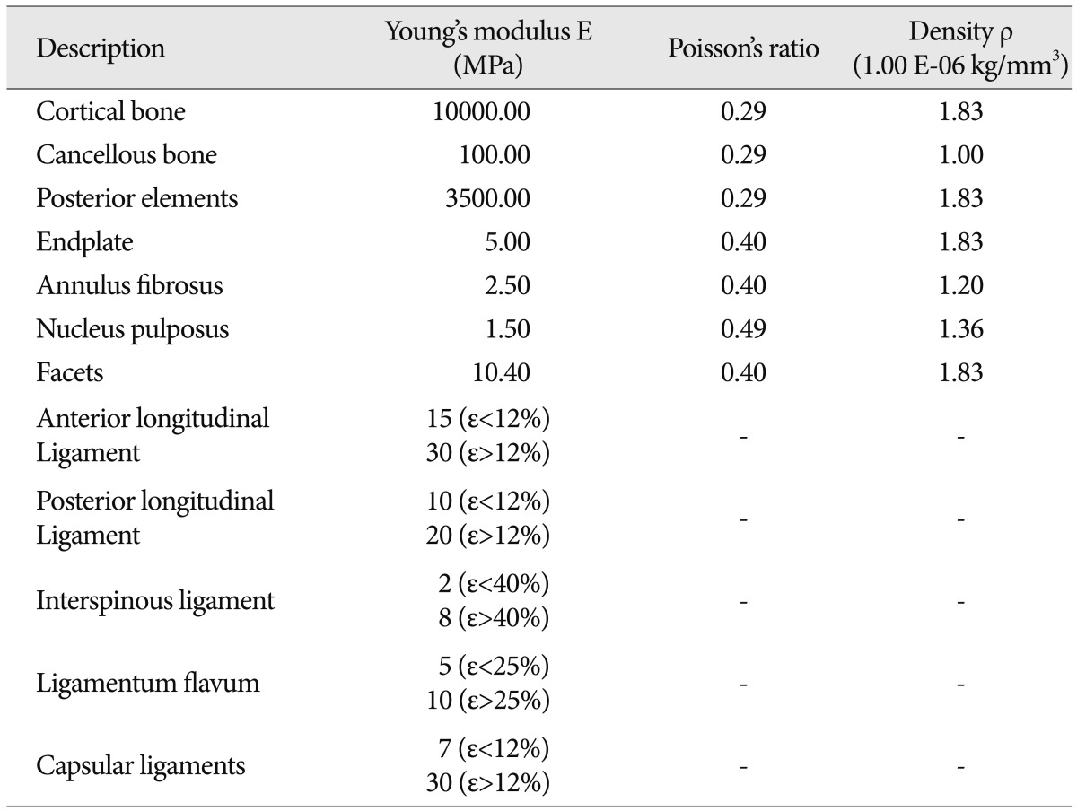
A previously validated three dimensional poro-elastic finite element model of an intact C6-7 cervical spine segment was employed for this study. Detailed modeling and validation information has already been published and a brief description follows12). The model was developed using serial axial CT scans of a 38-year old normal female subject. The CT scan was imported into the three-dimensional medical imaging software, Mimics (Materialise N.V., Ann Arbor, MI, USA). The vertebral surface models were translated into solid models using another computer aided design software, Pro/Engineer (Parametric Technology Corporation, Needham, MA, USA). The vertebral solid models were then meshed in the FE software, ADINA (ADINA R & D Inc., Watertown, MA, USA) for the simulation. The disc was modeled with an elliptical shape by connecting the surfaces of inferior C6 endplate and superior C7 endplate. The anterior and posterior disc heights agreed with the anthropometric literature values25). The major and minor diameters of the elliptical disc and NP were taken from the literature, and the NP was positioned in center of the disc21,26,33,35). The vertebrae, endplates and the intervertebral disc were modeled as 3D solid element with free-form meshing. The facets were modeled as 3D solid moving contact surface element with free-form meshing between the superior and the inferior surfaces. Five ligaments : anterior longitudinal ligament, posterior longitudinal ligament, interspinous ligament, ligamentum flavum and capsular ligaments were modeled. Ligament insertion points and area were closely matched with published data27,39). The cortical bone, cancellous bone, posterior elements, endplates, annulus fibrosus, nucleus pulposus and articular facets were assumed to be linear elastic, homogeneous and isotropic. The five spinal ligaments were assumed to be non-linear elastic. Material properties for different structures of the motion segment were adopted from the literature (Table 1)3,6,20,22,34).
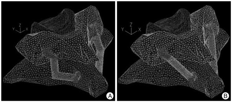
Two additional models were created by modifying the intact model to simulate C6C7 posterior fixation constructs using intralaminar screw with and without offset connector at C7 vertebra. 3.5 ├ś├Ś14 mm screws were inserted into the lateral mass of C6 vertebra while 3.5 ├ś├Ś24 mm screws were inserted into the lamina of C7 vertebra (Fig. 1).
Screws and the connecting rod were modeled as 3D solid elements with free-form meshing. Screws were approximated as cylinders with a Young's modulus of 100 GPa and were rigidly connected to the vertebrae. The connecting rods and offset connectors were also modeled as cylinders and were rigidly connected to C6 and C7 screws. Elastic modulus of the connecting rod was adjusted to 300 MPa to allow for the motion of the connecting rod at the screw-connecting rod joint in the real scenario.
The inferior face of the C7 vertebra was constrained in translation along the three principal planes. Moments were simulated by the application of two equal and opposite point loads on the superior surface of the C6 vertebra. 1.5 Nm flexion moment, 1.5 Nm extension moment, ┬▒1.5 Nm lateral bending moment and ┬▒2.0 Nm axial rotation moment were applied to the C6-7 segment one by one.
Model validation
The intact finite element model was validated by comparing the range of motion (ROM) results against the cadaver study results10). The cadaver study method is explained briefly below.
Ten fresh frozen human cadaver spines spanning from C5 to T1 were obtained. Donor criteria excluded subjects with history of spine trauma, osteoporosis, or any other bony diseases or radiation to the spine area. Any attached soft tissue not needed in the test was removed, carefully preserving the joint capsules and ligaments. C5 and T1 vertebral bodies were potted in a polymethylmethacrylate fixture in a manner that maintained the physiological motion from C6 to C7 and neutral and sagittal balance. The specimens were stored wrapped in saline-soaked gauze at -20Ōäā until the day before testing, when they were allowed to thaw overnight in a +4Ōäā refrigerator for 24 hrs.
Each specimen was mounted on a custom-built test frame designed to apply pure moments to a loading arm attached to the potted fixture on top of the C6 vertebral body. Pure moments along flexion/extension (1.5 Nm), lateral bending (1.5 Nm) and axial rotation (2.0 Nm) were applied. All moments were applied as a continuous load in order to produce smooth motion data with the Motion Analysis camera system. Vertebral motion was measured with a motion capture system (Motion Analysis Corp., Santa Rosa, CA, USA) by tracking a set of reflective markers attached to the C6 and C7 vertebral bodies. ROM and rigid-body kinematics were calculated using dedicated analysis software (EvaRT 4.2, Motion Analysis Corp.).
RESULTS
Model validation
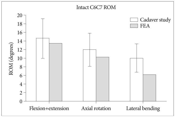
The comparison of ROM results from the cadaver study with finite element model is shown in Fig. 2. The finite element model ROM under flexion/extension and axial rotation moment corresponded well and were within one standard deviation of the cadaver study results. Lateral bending result from finite element model was 10% lower than one standard deviation of the cadaver results.
Changes in range of motion
Both the C6C7 posterior fixation techniques significantly reduced the ROM compared with the intact motion segment under flexion, extension, axial rotation and lateral bending. Biomechanical comparison of the two fixation constructs was performed using percentage ROM (PROM) defined as :
PROM=(ROM after Instrumentation/ROM for Intact Segment)├Ś100
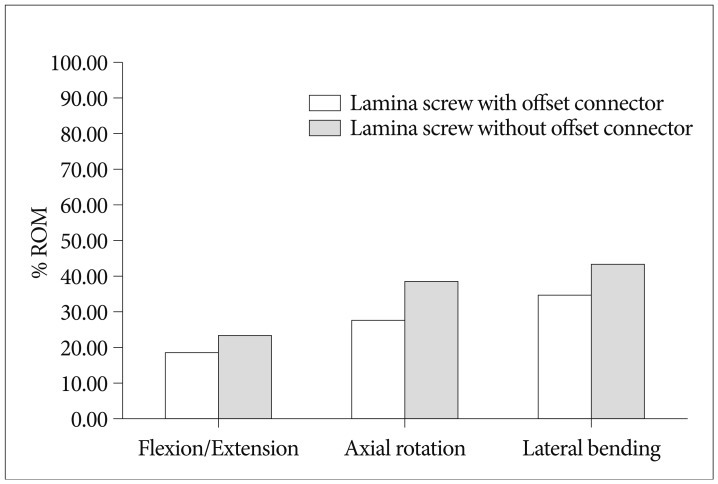
ROM for intralaminar screw construct with offset connector was less than the construct without the offset connector under all loading modes. PROM for construct with offset connector was 18%, 27% and 34% as compared to 23%, 38%, and 43% for construct without offset connector under flexion/extension, axial rotation and lateral bending respectively (Fig. 3).
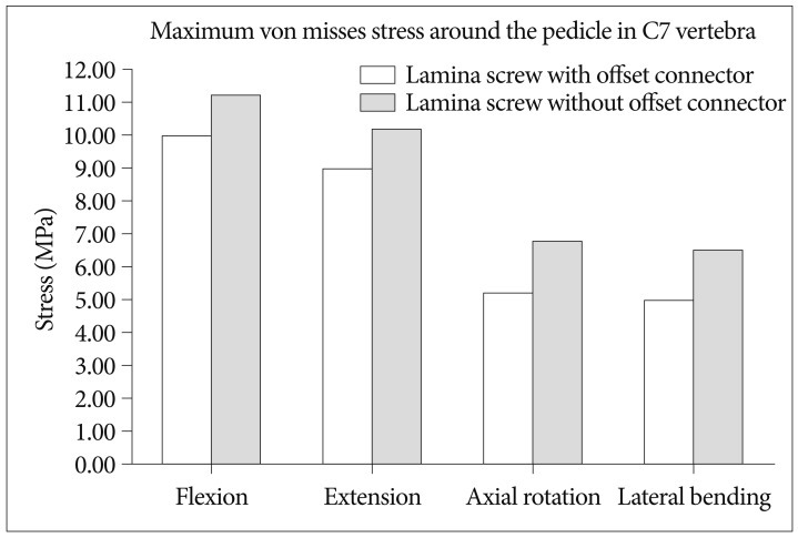
Stress in the vertebrae
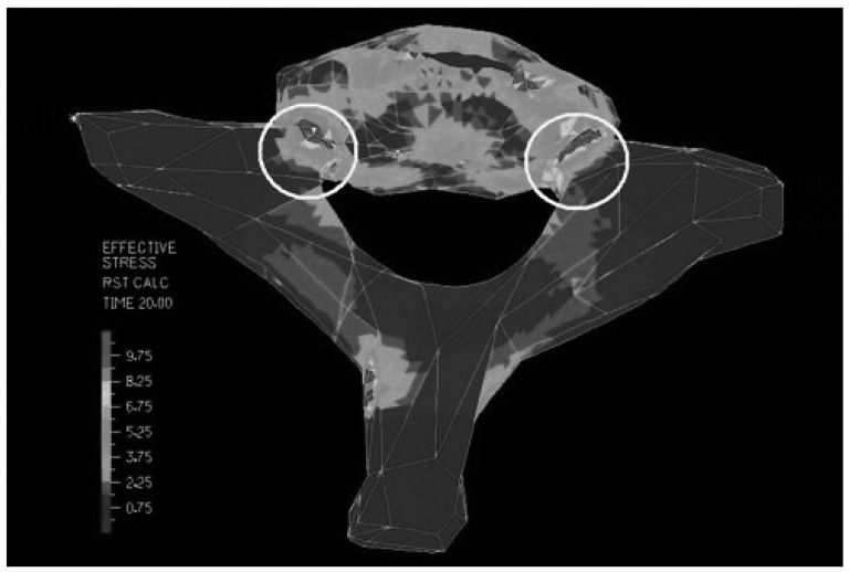
The maximum von Misses stress was observed in the C7 vertebra around the pedicle in both constructs under all loading conditions (Fig. 4). Maximum von Mises stresses in the construct without offset connector were observed to be 12%, 13%, 31% and 30% higher than the construct with offset connector under flexion, extension, axial rotation and lateral bending respectively (Fig. 5). Highest von Misses stress was observed under flexion, followed by extension, axial rotation and lateral bending respectively.
DISCUSSION
The current study employed a finite element model of a C6-7 human spinal segment to compare the kinematics and the maximum stress in the vertebra for intralaminar screw constructs with and without the offset connector. Validation study demonstrated excellent comparison with kinematics data from cadaver study. This study showed that both the fixation systems adequately stabilize the C6-7 segment in flexion, extension, lateral bending and axial rotation. However, construct with the offset connector performed better in terms of restricting the angular motion and exposed the vertebrae to lower level of stresses.
It is important that this result is kept within the context of its limitations. For example, the forces exerted by muscle in the physiological situation cannot be modeled in the laboratory. Furthermore, the relationship between stability and its effect on the bone fusion has not quantified yet in the cervical spine. And also, the computation model does not take into account anatomical parameter variations of lamina of each patient. Future research will involve the development of a model that will incorporate changes in muscle force and their mechanical influence on various surgical techniques. Another drawback of FE model testing is that this data cannot guarantee long term stability. Future studies on fatigue tests and clinical data will throw more light on long term stability and fusion rate.
CONCLUSION
The current study demonstrated that the intralaminar screw fixation with offset connector is better than the construct without offset connector in terms of biomechanical stability. Construct with the offset connector reduces the ROM of C6-7 segment more significantly compared to the construct without the offset connector and causes lower stresses around the C7 pedicle-vertebral body complex.